May 01, 2015

Experimenting with web-based Arduino Mega remote control

The major benefit of an Arduino Mega over smaller Arduino0-compatible boards is the extra volume of GPIO pins, and in conjunction with an Ethernet shield these can be controlled remotely via a web page thanks to the tutorial by the Starting Electronics website.

They have neatly explained how to control an Ethernet-enabled Arduino Mega using a HTML interface with Ajax along with some CSS and Javascript. The HTML file is stored on an external memory card connected to the Mega board. For a neat demonstration check out the following video:

For more information including the code and other interesting notes, visit the tutorial's home page. And for more, we're on facebook, twitter and Google+, so follow us for news and product updates as well.

If you're interested in using an Arduino Mega with Ethernet, a microSD card and more - it's time to upgrade to the Freetronics EtherMega:


Quite simple the EtherMega is the fully-loaded Arduino-compatible board on the market today. Apart from being completely Arduino Mega2560-compatible, it includes full Ethernet interface, a microSD card socket, full USB interface, optional Power-over-Ethernet support and still has a circuit prototyping area with extra I2C interface pins. So if your project is breaking the limits, upgrade to the EtherMega today.

April 29, 2015

Easily interface an Arduino with a Raspberry Pi

Although the Raspberry Pi is a great single-board computer and a lot can be accomplished with it, there are some instances where an Arduino or compatible board may be preferable, as they offer an inexpensive method of interfacing with a wide variety of hardware. However when you combine the two, the features of both units can be harnessed for more detailed projects.

One method of connecting the two has been demonstrated by Instructables member patsquare, whose project is a Raspberry Pi controlling a LCD via an Arduino. The method of connection is via the Arduino's USB port, which offers an easy way to send serial data between the two boards without needing level shifters etc. Example code has been provided in python for the Pi and of course the Arduino sketch, and is a neat framework for Pi to Arduino control. A quick demonstration of the project is shown in the following video:

For more information please visit the project's Instructable page. And for more, we're on facebookGoogle+, and twitter - so follow us for news and product updates as well.

For more complex Raspberry Pi projects that require interaction between an Arduino and a Raspberry Pi for enhanced hardwre control you can save time and space by using our new PiLeven board:

The PiLeven is an Arduino-compatible board based on the Arduino Uno, but with a few changes. Obviously it's a bit of a strange shape! The PiLeven fits right on top of a Raspberry Pi (either model B or B+) using the Raspberry Pi expansion headers.

The PiLeven also has a high-current switchmode power supply, so you can plug in anything from 7V to 18Vdc using the standard 2.1mm jack. The PiLeven can power the Raspberry Pi, so you don't need a regulated 5V USB connection anymore.

Serial communications on the PiLeven is linked through to the Raspberry Pi, so your Pi can upload new sketches straight to the PiLeven or send/receive data and commands. We've included level shifters so the 3.3V Pi can talk safely to the 5V PiLeven. And you can plug standard Arduino shields right into the PiLeven, giving your Raspberry Pi access to the huge range of shields already available. For more information about the PiLeven, including our tutorials - and to order yours today, visit the PiLeven webpage.

April 28, 2015

Build an Arduino-powered Network Time Synchronised Clock with ESP8266

If you're interested in having an incredibly accurate clock in your home or workplace, it's possible to make your own with an Arduino or compatible board that can retrieve the correct time from a network time server over the Internet using the Network Time Protocol. Doing so is quite simple, with only an Ethernet-enabled Arduino and a display of some sort to keep you updated.

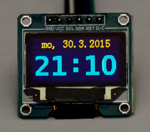
A neat example of an NTP clock has been demonstrated by Instructables member kariaa who uses the inexpensive ESP8266-based serial module as a bridge between the Arduino-compatible board and the Internet's time servers. The code is quite simple and gives you the framework for all sorts of accurate time pieces, such as the example below:

Furthermore the correct interfacing method for the ESP8266 to the Arduino is explained well. To get started, visit the clock's Instructable page. And for more, we're on facebookGoogle+, and twitter - so follow us for news and product updates as well.

If you're starting out with ESP8266 WiFi serial modules, save time and eliminate risk by using our new ESP-01 WiFi Module shield for Arduino:

Our new shield has a socket that's perfect for the ESP-01 module, and addresses all the needs of the ESP8266 - such as:

  • 3.3V regulator dedicated to the module to ensure sufficient current capacity
  • Logic level shifters on TX/RX lines: compatible with both 3.3V and 5V Arduino models
  • Selectable TX/RX pins: use D0/D1 for hardware serial, or D2 - D7 for software serial
  • CH_PD pin on ESP-01 module pre-biased for correct operation mode
  • Extra ESP-01 pins broken out for your own connections
  • Prototyping area with 5V and GND rails
  • All Arduino headers broken out for easy connections
  • Stacking R3-style Arduino headers including the ICSP header

So don't fiddle with jumper wires or sub-standard power supplies - order your the Freetronics ESP-01 WiFi Module Shield today. They're in stock right now for only $14 including GST.

April 27, 2015

Avoiding LEGO train accidents with Arduino

Next in the series of ongoing tutorials for the beginner from the Arduino LEGO Trains YouTube channel is a neat explanation of how to use an Arduino and some simple sensors to ensure two trains cannot crash while using a pair of crossovers in a LEGO train layout. This type of layout can offer two loops to allow for two trains to run at once, without any damaging consequences of an accident.

The Arduino acts as a finite state machine, and with the aid of the light sensors which detect oncoming trains to the crossing - one train loop can be shut down until the other train passes or a set amount of time has elapsed. Enjoy the following video for an interesting demonstration of what is possible:

For more interesting LEGO train videos, subscribe to their YouTube channel. And for more, we're on twitter, facebook and Google+, so follow us for news and product updates as well.

And for more, we're on facebookGoogle+, and twitter - so follow us for news and product updates as well.  

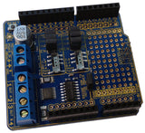
 If you're looking into starting with Arduino and motor control, such as the 9V LEGO trains shown in the video above from your Arduino or compatible, check out our HBRIDGE: DC/stepper motor shield. Based around the powerful Allegro A4954 H-bridge driver IC you can control two DC motors with complete ease, or one bipolar stepper motor. With connections for external power management, a complete beginners' guide and documentation - motor control couldn't be any easier. For more information and to order, visit the HBRIDGE: page.

April 23, 2015

Concurrently monitor data from multiple Raspberry Pis with Initial State

Using a combination of a cloud-based data visualisation service and multiple Raspberry Pi computers you can easily monitor data from each Pi concurrenlty on the one screen - ideal for monitoring various sensors placed in multiple sites. A few years ago this may have seemed impossible or very expensive, however nothing could be further from the truth.

The people from Initial State - "a technology startup helping engineers capture and understand product data" - have produced a neat tutorial that explains how to use popular DS18B20 digital temperature sensors each with a Raspberry Pi, and how to send the data back to their cloud service. Both hardware and software requirements are explained which will have your system working very quickly, and leave you with a neat and useful dashboard - for example:

For complete information on this project, and other interesting ideas - visit the Initial State website. And for more, we're on facebookGoogle+, and twitter - so follow us for news and product updates as well. 

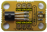
If you're interested in measuring termperature with a reliable sensor - consider using our TEMP: DS18B20-based temperature sensor module:

The TEMP: uses the Dallas DS18B20 1-wire digital temperature sensor, with a wide measurement range of -55 to +125°C at an accuracy of +/- 0.5°C. For more information, tutorials and to order - visit the TEMP: page

April 22, 2015

alertR - the Raspberry Pi unified alerting system

After starting to build an alarm system based on a Raspberry Pi, Andrew Pawlowski realised that so much more was possible, and as created a neat unified messaging system which can be used in all sorts of applications. His system - named "alertR" - can be integrated with all sorts of devices and control a wide variety of devices.

Furthermore a sequence of control based on various events can be setup to make life easier - for example if a doorbell is pressed the volume on a sound system can be reduced, or a security camera could take an image. Check out the following video for more information: 


Finally Andrew has made his project open-source, so you can find out more by starting with his github page. And for more, we're on facebookGoogle+, and twitter - so follow us for news and product updates as well.

If you're looking for a neat way to add external circuitry to your Raspberry Pi model A+, B+ or 2 model B then check out our new PiBreak Plus Raspberry Pi Prototyping Board:

This is a great way to add your own electronic components, circuitry, sensors or other devices to your Raspberry Pi model A+, B+ or 2 Model B - any of the current Raspberry Pis with a 40 pin GPIO header. The PiBreak Plus also includes a GPIO female header to solder yourself, and a pair of nuts, bolts, washers and spacers to ensure a a great fit.

And in the Freetronics fashion we've used a quality gold-plated (ENIG) PCB for durability, brought out all the power rails along with the GPIO next to the prototyping area to make adding circuits a breeze. Furthermore the pinouts are labelled on both the top and bottom of the PCB to save time referencing the right GPIO pins. For more information and to order - visit the PiBreak plus page now!

April 21, 2015

Examine simple waveforms with the Arduino-powered notscilloscope

Next in our line of interesting Arduino-based test equipment projects is the "notscilloscope" by Augusto Campos. This is a neat way to display the amplitude of a signal over time - just as you could with an oscilloscope, however at a slower speed. However this is still a neat way to not only practice your Arduino skills but also understand the basics of how an oscilloscope works.

The notscilloscope can measure waveforms that fall between zero and near the operating voltage of the Arduino or compatible board being used, with the user being able to adjust the centre of the display and also the default amplitude - and an "auto" button can quickly optimised the display of currently-measured data. Check out the following video for a neat demonstration:

For more information and the Arduino sketch, visit Augusto's github page. And for more, we're on facebook, twitter and Google+, so follow us for news and product updates as well.

If you're looking for a neat and colourful display to use with your Arduino or Raspberry Pi - consider our 128x128 pixel OLED Module. With a diagonal size of 1.5" and 16,384 colours to select from, so almost anything is possible. Furthermore there's a microSD card socket, and removable tabs on each side which can hold LEDs and buttons:

And using the module is made simple - we have tutorials and drivers for both the Arduino and Raspberry Pi platforms - great for experimenters or those who use both systems. Furthermore, check out the forum where members are already creating modified drivers to rapidly increase the display speed. For more information including our Quickstart guides - and of course to order - visit the OLED Module product page.

April 20, 2015

Make an Arduino-powered Ohm Meter

As we always say at Freetronics - making your own test equipment is always a fun and educational process - as you can not only create something that is useful, along with learning a lot more about the targets of the equipment. Another great example of this is by Ritik Bhardwaj who shows how incredibly simple it is to make an Arduino-powered Ohm-meter (a device to measure the value of a resistor).

The device works on the principle of the voltage divider circuit, and with a little algebra and know input voltage (say 5V from the Arduino) it can calculate the resistance of the compinent under test. It's quite simple and it works, and a neat way to experiment with voltage dividers and electronics theory. The value of the resistor under test can be sent to the serial monitor or to an LCD as shown below:

For more information on making your own version, visit the project's Instructable page. And for more, we're on facebookGoogle+, and twitter - so follow us for news and product updates as well.

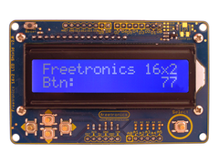
Looking for a rapid-use LCD for your Arduino or compatible development boards such as the example above? Save time and move forward with the Freetronics LCD & Keypad shield which contains a bright 16x2 character LCD and five buttons that can be read from only one analogue input pin:

April 16, 2015

Experimenting with Android control of Arduino via Bluetooth

The ability to have a smartphone interact with an Arduino-based project is certainly a great feature to harness, however the process of doing so may seem overwhelming - especially creating the app for the Android device. However thanks to the free MIT App Inventor software - a graphical drag-and-drop development environment, you can easily make your own Android apps that can communicate with a Bluetooth-equipped Arduino.

To make this even easier, the people from ForceTronics have explained not only the hardware connection between the Arduino and Bluetooth module - but also provided the code for both the App Inventor and Arduino sketch. Finally the method of creating a simple Android app to toggle a digital output on the Arduino is shown in the following video:

This offers you the gateway to more interactive projects and adding a professional user-interface, so to learn more visit the tutorial website. And for more, we're on facebookGoogle+, and twitter - so follow us for news and product updates as well.

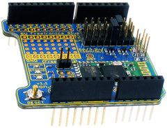
As part of the Arduino and Bluetooth experience you'll need a Bluetooth device for your Arduino projects, and to meet this need we've released our new Freetronics Bluetooth Shield:


We've made it simple to use - the Bluetooth Shield acts as a serial link between the other Bluetooth device. Furthermore there's a wide range of jumpers allowing you to select which digital pins to use for data transfer, increasing compatibility with other shields. And with our Quick Start guide it's easier than ever.

Our Bluetooth Shield for Arduino is now in stock and ready to ship, so for more information and to order - visit the shield's product page.

April 15, 2015

Make your own Arduino-controlled "Egg Bot"

The "Egg Bot" is a robot kit from Evil Mad Science that offers the ability to draw patterns on to an egg or similarly-shaped object. And thanks to the open-source nature of the project there are several variations being published, one of which by Nikodem Bartnik.

This version is just as simple to make as the original, and relies on a limited amount of hardware which you can locate quite easily in hardware stores and other suppliers. When it comes time to print on the egg, the design is created in the open-source drawing program Inkscape with the Egg Bot extension, which generates the necessary files to be sent to the Arduino-based hardware and electronics. A neat demonstration of Nikodem's version can be seen in the following video:

For complete details on making your own version, check out Nikodem's Instructable page. And for more, we're on facebookGoogle+, and twitter - so follow us for news and product updates as well.

If you're looking to develop projects based on an Arduino that use stepper motor, CNC machines on a larger scale, and much more - simplify the process with our Freetronics StepDuino board:

The StepDuino is a complete, self-contained Arduino-compatible board with 2 onboard stepper motor drivers, 2 servo outputs, a 20x4 LCD, a micro SD card slot, and more! It's a fantastic general purpose board for any project that uses stepper motors. You can use it as the brain of your next robotics project!

The StepDuino uses the same processor architecture as the common Arduino Uno, so you can program it right from the Arduino IDE simply by selecting "Arduino Uno" as the board type. Everything simply works out of the box, just as it would with a regular Arduino - but now you can also drive steppers directly and display feedback on the huge LCD. For more infromation, tutorials and to order - visit the StepDuino page.