


Have you ever wondered why Arduino boards have bizarre spacing between the top headers?
The reason is that back in 2005, the design for one of the very first Arduino boards was being finished late one night so that it could be sent to a PCB factory the next day, and Massimo Banzi accidentally bumped the location of the D8-D13 header slightly sideways off the 0.1" grid that he used to lay out the parts. He didn't notice when looking at the design on the computer screen, so when the PCBs came back from the factory with the header in the wrong position they decided to just use them anyway.
After this first batch of PCBs had been used up the header could have been moved into the correct position for the next batch, but by then it seemed like it would be too disruptive to change the design and break compatibility with the projects they had already made using the first boards. So the decision was made to leave it there, and we've been stuck with bizarre header positions ever since.

For many people it's frustrating because you can't use regular 0.1" prototyping board to make your own shields, but this little accident of history had a good side effect: it makes the Arduino header format only work one way. You can still put a shield into the wrong position, but most of the time it takes extra force to insert it.
Some types of headers and connectors have a mechanical "key" that prevents them being misaligned or inserted backwards, but not all headers have this benefit. Many headers are symmetrical, so they can be accidentally inserted backwards or offset to one side.
Danny Vagg was pondering how to solve this problem after he accidentally inserted a Zigbee board into the wrong holes and damaged the board, with a higher voltage being applied to a pin that could only operate at 3.3V.
To prevent it happening again, Danny came up with a very easy solution for making your own keyed headers. Danny's suggestion is:
1. Select a pin that you don't need to use, and cut it off.
2. Cut off a short length of wood skewer, and split it lengthwise to make it narrower.
3. Insert the small piece of wood skewer into the matching hole in the header.
By leaving the wood slightly longer so that it protrudes from the header, it's easy to remove it again later if you need to.
In this photo Danny inserted skewers into the NC, IOREF, VIN, A6, and A7 pins of an EtherMega. On his shield (not shown) he's left off those same pins to allow the shield to only be inserted in the correct position:
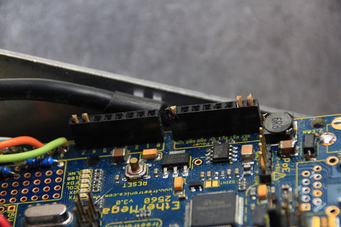
Now the headers can only be inserted in the correct position, and it'll be impossible for you to push the board in the wrong place.
And because he specifically selected unused power pins for the key locations, it reduces the chance of a shield pin being connected accidentally to a higher voltage than the shield rating.
The NC (not connected) and VIN pins are particularly good ones to pick if you want to add keys to your header. The NC pin isn't used by any current Arduino design, and the VIN pin can often expose 12V or more which can be enough to damage some parts that are designed to operate at 5V or 3.3V.
Thanks for the tip, Danny! We'll send you a prize for your suggestion.


