


A common barrier faced by many new electronics hobbyists is understanding exactly how a breadboard works. Fortunately with a simple explanation and some practice this is a skill that can be quickly mastered. Although breadboards can be found in many configurations a common format is shown below:
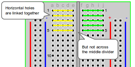
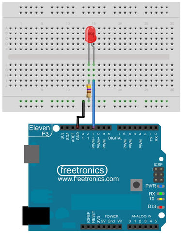
As you can see on either side of the bread board are two columns (usually referred to as power rails) and on both sides of a central divider (used for bread boarding ICs), horizontal rows of connected holes. Each row or rail is a “node” of the circuit meaning that the voltage at any point of the same “node” will be the same. It is for this reason that different component pins are usually connected between different rows or rails and not on the same one (otherwise they would have 0V across them!). For example, the following circuit is from our Experimenter’s Kit and highlights where electrical connections are present with green lines:
If you are still struggling to master the art of breadboarding you can find a more thorough explanation at the following link.
Working on a project you want us to feature in this blog? Had success with breadboarding in the past? Let us know in the comments section below or on Facebook and Twitter.


