


The Security Sensor Shield is an Arduino-compatible shield that allows you to connect up to four security sensors such as passive infra-red (PIR) motion detectors.
This shield implements exactly the same circuit as the "Security / Automation Sensors" project documented in the book Practical Arduino, so it will work perfectly with the example software in that project. You can learn more about it at:
www.practicalarduino.com/projects/security-sensors
Hardware Setup
Each sensor should be connected to the shield using a 4-core security cable. One pair of the cable is used to carry 12Vdc power to the sensor, and the other pair is used to detect sensor status.
1. Fit the Security Sensor Shield to your Arduino.
2. Use 4-core security cable to connect the "+" and "-" terminals on a sensor to the "+" and "-" terminals on one of the sensor channels on the shield.
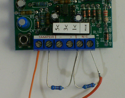
3. Connect a 4K7 resistor across the "NC" (normally closed) terminals of the sensor, as shown in the photo below.
4. Connect a 4K7 resistor between one NC terminal and one of the tamper terminals.
5. Use the other pair of the security cable to connect from the other tamper terminal and one of the NC terminals to the "Sensor" terminals on the Security Sensor Shield.
6. Repeat steps 2 through 5 for each sensor.
7. Connect a 12Vdc power supply to the "+" and "-" terminals of the "Sensor Power Supply" screw terminals, and turn it on. Check that the sensors each receive power.
You can either insert the resistors into the screw terminals as shown, or solder them permanently onto the back of the sensor PCB to make it easier when fitting the wires and mounting the sensor in place.
Connect 12Vdc Power Supply
If your sensors require a power supply you can connect the output from a 12Vdc plug pack or other power supply to the “Sensor Power Supply” screw terminals on the end of the shield. Applying power to the plug pack will cause the green LED to illuminate, and sensors connected to the + and – terminals will power up.
Load Test Sketch
Schematic


