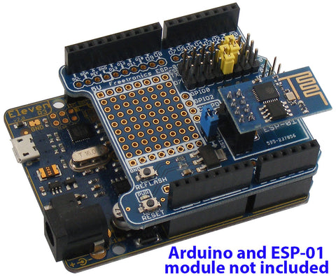
The ESP-01 WiFi Module Shield provides a convenient connection between an Arduino and an ESP-01 module, which contains an ESP8266 microcontroller with WiFi support. The shield provides a 3.3V power supply for the module, and logic level converters so it can operate with either 3.3V or 5V Arduino boards.

Note: There have been 3 versions of the shield released. Some of the features noted in these instructions may not apply to your version of the shield. You can check the shield version in the bottom right corner of the PCB, near header A5:

v1.0: Initial release.
v2.0: Added onboard 3.3V regulator to ensure enough current is available for the ESP-01 even when connected to an Arduino with a small 3.3V regulator. Added bias resistor to CH_PD line to enable normal run mode by default for ESP-01 modules with standard firmware installed.
v3.0: Added a "REFLASH" button to allow simple reflashing of the firmware on the ESP-01. Added a jumper for easy isolation of the reset line.
Hardware Setup
1. Mount the shield on your Arduino.
2. Mount your ESP-01 module on the shield using the header provided. The module must be oriented to align with the marking on the shield.
3. Configure the serial jumpers near the top right of the shield to suit the pins your Arduino will use for communication with the ESP-01 module. The module ships with jumpers in a default position as shown above to connect the module's TX line to Arduino pin D2, and the module's RX line to Arduino pin D3. This means your Arduino will need to transmit on D3 (to the module's RX line) and receive on D2 from the module's TX line.
4. Configure the reset jumper to connect module reset to Arduino reset. With the jumper in place (labelled "RST-LNK" on the PCB) the module's reset line is connected to the Arduino reset line, so when you press the Arduino RESET button your module will also be reset. This is a good way to ensure the module always starts in a known state when your Arduino resets. However, if you wish to isolate your module from Arduino reset you can remove the RST-LNK jumper. The jumper is fitted by default.
Software Setup
The software required to use your ESP-01 depends on the firmware it has installed. The most common firmware shipped on the modules provides a WiFi bridge that can be controlled via "AT" serial commands from your Arduino. You can therefore use your Arduino as a "serial reflector" to pass commands and responses between your computer and the module, allowing you to type commands in the Arduino IDE serial console and see how the module replies.
If your ESP-01 module has different firmware installed it may operate totally differently, and these instructions won't apply.
If your ESP-01 module is running the default firmware, open the Arduino IDE, create a new sketch, and paste in the following code:
/**
 * SerialReflector
 */
#include <SoftwareSerial.h>

SoftwareSerial device(2,3); // Rx, Tx

void setup() {
  Serial.begin(115200); // Serial port for connection to host
  device.begin(115200); // Serial port for connection to serial device } void loop() {   if(device.available())   {     Serial.write(device.read());   }   if(Serial.available())   {     device.write(Serial.read());   } }
This sketch opens a serial connection to your computer via USB at 115200bps, and also opens a software serial connection to the ESP-01 module via pins D2 and D3. Any data sent to one serial port is then retransmitted to the other port, allowing messages to pass transparently through your Arduino between your computer and the module.
In the Arduino IDE, select "Tools -> Serial Monitor" to open the serial monitor, and check that the speed is set to 115200bps in the bottom right corner. Also make sure the line-ending dropdown says "Both NL & CR".
Type "AT+RST" and press ENTER. This tells the ESP-01 module to restart. After startup the default firmware will output information about its version, then say "ready".
You can now send AT commands to your ESP-01 module and see the responses.
Reflashing ESP-01 Firmware
The default firmware installed on ESP-01 modules implements a serial-to-WiFi bridge that can be controlled using AT commands.
To install new firmware, the ESP-01 must be rebooted into a special mode that allows it to accept a new firmware image via its serial interface. This is done by pulling the GPIO0 pin LOW (0V) while the module is starting up. Using a jumper wire, make a temporary connection between one of the GND pads on the shield, and the GPIO0 breakout just to the right of the prototyping area. Press RESET, and your module will now reboot into flashing mode.
You can install new firmware by following tutorials such as:
www.instructables.com/id/Intro-Esp-8266-firmware-update/
Note: Up to version v3.0 of the shield, the "REFLASH" button pulls the CH_PD pin LOW as required by early ESP-01 modules. From v3.1 of the shield onwards, the "REFLASH" button pulls GPIO0 LOW instead, as required by currently shipping versions of the ESP-01.


