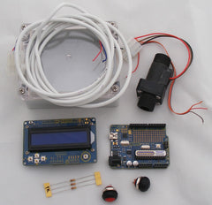
Water conservation is critically important in many parts of Australia, but it's hard to reduce consumption of something when you can't measure your usage. This project combines a Hall-effect water flow gauge with a Freetronics "Eleven" Arduino-compatible board and an LCD to make it easy for your to measure water consumption in your shower, bath, or other parts of the house.

The operational principles of this project are documented in detail in the book Practical Arduino, available from your local Jaycar store, so for more information please see the book. The photograph above shows how the project was built for the book using discrete parts from Jaycar, but we'll show you a newer, even easier way to build it using a pre-built 16x2 LCD Shield.
Parts Required
Instructions
Fit LCD Shield
This project can also be built using a separate HD44780-compatible 16x2 LCD module as described in Practical Arduino, but it can be very fiddly soldering all the connections in place so it's far easier to use the 16x2 LCD Shield. Simply plug the shield into the top of the Arduino and you're ready to go.

Follow the instructions in the Getting Started guide for the 16x2 LCD Shield and run one of the demonstration sketches to verify that it's correctly connected and operational.
Prepare Flow Sensor
The Hall-effect flow sensor comes with short cables, and it may be fitted with a plug that you can't use. The simplest solution is to cut off the existing plug and attach an appropriate length of flexible cable, either soldered directly to the sensor wires (preferably with heat-shrink tubing to cover the joints) or by using a 3-way plug and socket pair such as the one linked in the parts list.
The recommended Hall-effect flow sensor has three connections:
- Ground (black)
- Power (red)
- Signal (brown)
Take note of which colours in the cable represent each connection to the sensor. To avoid confusion it's best to match up the colours if possible, but if your cable has different colours just match them as best you can and write a note of what each colour means.
Prepare Project Box
If you will be mounting your project in a box, now is the time to think about how everything will fit and where you will connect external cables. If you choose a case with a transparent lid you can simply mount the Eleven in the bottom of the box using plastic stand-offs and small nuts and bolts, with the LCD visible right through the lid.
Remember to allow space for the sensor cable to enter the case, as well as a USB or power cable to connect to the Eleven. It's easiest if you can insert a USB cable while everything is in place, because then you can connect the flow gauge to your computer to update the software without having to disassemble it first.
Drill holes in the box for the sensor cable and power / USB cables to pass through, and mount the Eleven in place. You can see here the Eleven partly mounted using 15mm M3 bolts, nylon washers, and 6mm plastic spacers available from Jaycar. The hole for the USB cable has also been drilled.

Once the Eleven has been securely mounted, fit the 16x2 LCD Shield in place on the headers.
Connect Flow Sensor
Insert the end of the Hall-effect flow sensor cable through a hole in the box. To prevent it being pulled back out and damaging solder joints you can then tie a knot in it, or put a cable tie very tightly around the cable just inside the box.

Strip back the end of the cable and prepare it for soldering to the 16x2 LCD Shield. The recommended Hall-effect sensors run on any DC supply from 2.4V to 26V, so they're perfect for running on the 5V available from the Arduino.
Solder the Ground lead to the top of one of the terminals marked "GND" on the 16x2 LCD Shield. Likewise, solder the Power lead to the terminal marked "5V".
The Signal lead needs to be connect to the terminal marked D2 via a 1K resistor. Note that the circuit will still function correctly if you don't use the resistor and instead connect the Signal lead directly to D2, but the resistor provides a bit of an insurance policy for the Eleven by helping to protect the digital I/O line in case anything goes wrong. It's generally a good design principle to include a low-value current limiting resistor in series with digital connections to external devices.

There are alternative ways to make the connections if you would prefer not to solder directly to the 16x2 LCD Shield. For example, you could stack a Terminal Shield underneath the 16x2 LCD Shield, and simply connect the sensor wires to the screw terminals with no soldering required.
Mount Buttons
While you are drilling holes in the box, also prepare the lid for the pair of pushbuttons. Before you drill those holes, though, make sure you check the clearance underneath! The buttons will protrude down into the box, so there needs to be enough space for them to clear the 16x2 LCD Shield inside.
Once the holes are drilled, fit the buttons and tighten their retention nuts. Test-fit that you can close the lid on the box without it fouling the 16x2 LCD Shield.
With the buttons mounted, solder short lengths of ribbon cable or other light hookup wire to the button terminals. Make sure the wire is long enough for you to be able to solder the other end to terminals on the 16x2 LCD Shield with the lid open: about 15cm is probably about right.

Connect Buttons
The buttons can now be connected, with one wire from each button soldered to a terminal marked GND on the top of the 16x2 LCD Shield. The other wire from each button is then connected via a 1K resistor to the terminal marked either D11 or D12. On our version we jumpered the GND connection across between the buttons so there are three wires going from the buttons to the 16x2 LCD Shield, with one being a shared GND.

Some heat-shrink tubing can be a good way to make sure there are no short-circuits on the soldered joints.
Assemble Case
All the parts are now in place, so fit the cover to the case and screw it closed. You're ready now to load the software.

Flow Gauge Sketch
The example sketch provides two independent flow counters, with one button resetting each counter.
Open the Arduino IDE, create a new sketch, and copy and paste the source code below into it. Save the sketch with a sensible name such as "WaterFlowGauge", select the correct serial port and board type as usual, and upload the sketch to your Eleven.
/**
 * Water Flow Gauge
 *
 * Uses a hall-effect flow sensor to measure the rate of water flow and
 * output it via the serial connection once per second.
 *
 * Copyright 2009 Jonathan Oxer <jon@oxer.com.au>
 * Copyright 2009 Hugh Blemings <hugh@blemings.org>
 *
 * This program is free software: you can redistribute it and/or modify
 * it under the terms of the GNU General Public License as published by
 * the Free Software Foundation, either version 3 of the License, or
 * (at your option) any later version. http://www.gnu.org/licenses/
 *
 * www.practicalarduino.com/projects/water-flow-gauge
 */

#include <LiquidCrystal.h>
// initialize the library with the numbers of the interface pins
LiquidCrystal lcd(8, 9, 4, 5, 6, 7);

// Specify the pins for the two counter reset buttons and indicator LED
byte resetButtonA = 11;
byte resetButtonB = 12;
byte statusLed    = 13;

byte sensorInterrupt = 0;  // 0 = pin 2; 1 = pin 3
byte sensorPin       = 2;

// The hall-effect flow sensor outputs approximately 4.5 pulses per second per
// litre/minute of flow.
float calibrationFactor = 4.5;

volatile byte pulseCount;

float flowRate;
unsigned int flowMilliLitres;
unsigned long totalMilliLitresA;
unsigned long totalMilliLitresB;

unsigned long oldTime;

void setup()
{
  lcd.begin(16, 2);
  lcd.setCursor(0, 0);
  lcd.print("                ");
  lcd.setCursor(0, 1);
  lcd.print("                ");

  // Initialize a serial connection for reporting values to the host
  Serial.begin(38400);

  // Set up the status LED line as an output
  pinMode(statusLed, OUTPUT);
  digitalWrite(statusLed, HIGH);  // We have an active-low LED attached

  // Set up the pair of counter reset buttons and activate internal pull-up resistors
  pinMode(resetButtonA, INPUT);
  digitalWrite(resetButtonA, HIGH);
  pinMode(resetButtonB, INPUT);
  digitalWrite(resetButtonB, HIGH);

  pinMode(sensorPin, INPUT);
  digitalWrite(sensorPin, HIGH);

  pulseCount        = 0;
  flowRate          = 0.0;
  flowMilliLitres   = 0;
  totalMilliLitresA = 0;
  totalMilliLitresB = 0;
  oldTime           = 0;

  // The Hall-effect sensor is connected to pin 2 which uses interrupt 0.
  // Configured to trigger on a FALLING state change (transition from HIGH
  // state to LOW state)
  attachInterrupt(sensorInterrupt, pulseCounter, FALLING);
}

/**
 * Main program loop
 */
void loop()
{
  if(digitalRead(resetButtonA) == LOW)
  {
    totalMilliLitresA = 0;
    lcd.setCursor(0, 1);
    lcd.print("0L      ");
  }
  if(digitalRead(resetButtonB) == LOW)
  {
    totalMilliLitresB = 0;
    lcd.setCursor(8, 1);
    lcd.print("0L      ");
  }

  if( (digitalRead(resetButtonA) == LOW) || (digitalRead(resetButtonB) == LOW) )
  {
    digitalWrite(statusLed, LOW);
  } else {
    digitalWrite(statusLed, HIGH);
  }

  if((millis() - oldTime) > 1000)    // Only process counters once per second
  {
    // Disable the interrupt while calculating flow rate and sending the value to
    // the host
    detachInterrupt(sensorInterrupt);
    //lcd.setCursor(15, 0);
    //lcd.print("*");

    // Because this loop may not complete in exactly 1 second intervals we calculate
    // the number of milliseconds that have passed since the last execution and use
    // that to scale the output. We also apply the calibrationFactor to scale the output
    // based on the number of pulses per second per units of measure (litres/minute in
    // this case) coming from the sensor.
    flowRate = ((1000.0 / (millis() - oldTime)) * pulseCount) / calibrationFactor;

    // Note the time this processing pass was executed. Note that because we've
    // disabled interrupts the millis() function won't actually be incrementing right
    // at this point, but it will still return the value it was set to just before
    // interrupts went away.
    oldTime = millis();

    // Divide the flow rate in litres/minute by 60 to determine how many litres have
    // passed through the sensor in this 1 second interval, then multiply by 1000 to
    // convert to millilitres.
    flowMilliLitres = (flowRate / 60) * 1000;

    // Add the millilitres passed in this second to the cumulative total
    totalMilliLitresA += flowMilliLitres;
    totalMilliLitresB += flowMilliLitres;

    // During testing it can be useful to output the literal pulse count value so you
    // can compare that and the calculated flow rate against the data sheets for the
    // flow sensor. Uncomment the following two lines to display the count value.
    //Serial.print(pulseCount, DEC);
    //Serial.print("  ");

    // Write the calculated value to the serial port. Because we want to output a
    // floating point value and print() can't handle floats we have to do some trickery
    // to output the whole number part, then a decimal point, then the fractional part.
    unsigned int frac;

    // Print the flow rate for this second in litres / minute
    Serial.print(int(flowRate));  // Print the integer part of the variable
    Serial.print(".");             // Print the decimal point
    // Determine the fractional part. The 10 multiplier gives us 1 decimal place.
    frac = (flowRate - int(flowRate)) * 10;
    Serial.print(frac, DEC) ;      // Print the fractional part of the variable

    // Print the number of litres flowed in this second
    Serial.print(" ");             // Output separator
    Serial.print(flowMilliLitres);

    // Print the cumulative total of litres flowed since starting
    Serial.print(" ");             // Output separator
    Serial.print(totalMilliLitresA);
    Serial.print(" ");             // Output separator
    Serial.println(totalMilliLitresB);

    lcd.setCursor(0, 0);
    lcd.print("                ");
    lcd.setCursor(0, 0);
    lcd.print("Flow: ");
    if(int(flowRate) < 10)
    {
      lcd.print(" ");
    }
    lcd.print((int)flowRate);   // Print the integer part of the variable
    lcd.print('.');             // Print the decimal point
    lcd.print(frac, DEC) ;      // Print the fractional part of the variable
    lcd.print(" L");
    lcd.print("/min");

    lcd.setCursor(0, 1);
    lcd.print(int(totalMilliLitresA / 1000));
    lcd.print("L");
    lcd.setCursor(8, 1);
    lcd.print(int(totalMilliLitresB / 1000));
    lcd.print("L");

    // Reset the pulse counter so we can start incrementing again
    pulseCount = 0;

    // Enable the interrupt again now that we've finished sending output
    attachInterrupt(sensorInterrupt, pulseCounter, FALLING);
  }
}

/**
 * Invoked by interrupt0 once per rotation of the hall-effect sensor. Interrupt
 * handlers should be kept as small as possible so they return quickly.
 */
void pulseCounter()
{
  // Increment the pulse counter
  pulseCount++;
}
Test Readings
You're ready to try it out! Note that the Hall-effect flow sensor is directional: if you look on the side of the body you'll find an arrow moulded into the plastic to indicate the direction of water flow.
With the Eleven powered up and the LCD showing the flow rate and counters, gently blow through the flow sensor to make the impeller spin. If everything is working as expected you'll see the flow rate number increase on the LCD, and the counters will begin to accumulate total flow volume.
Pressing either button will reset the associated counter, while leaving the other counter unchanged. Having two counters can be handy so you can do things like accumulate the total water usage in the shower for the day using one counter, and letting each member of the family reset the other counter to measure their individual water usage.
Install Flow Sensor
The flow sensor itself is manufactured from a very strong material consisting of a glass-fibre reinforced plastic resin. It has standard 1/2-inch BSP thread on each end, so you can screw it into standard plumbing fittings. Note that in many jurisdictions it's illegal to perform plumbing work yourself without the necessary license, so if you have a plumber install the sensor for you make sure you show them the direction marker on the sensor body so they know which way around to install it.
Variations
This project could also be built on a Freetronics EtherTen, which includes Ethernet connectivity. You could then record flow data and publish it to an online datalogging service such as Cosm.
We hope you've enjoyed this project, and please feel free to post in the Freetronics forum with any questions or to show off any Arduino projects you build!


