


The OLED128 128x128 pixel OLED display modules include a "wing" on each side, where you can optionally solder an LED and/or a button.
(If you're looking for a main OLED128 quickstart guide, check the separate guides for Arduino or Raspberry Pi.)
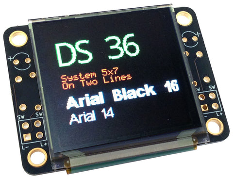
There is a separate pin header connection for each wing.
Parts you'll need
- Pushbuttons that are suitable for the "wings" are included in the OLED128 packaging.
- The LED footprints are designed for standard "3mm" through-hole LEDs (this is the most common though-hole LED size.)
- The resistor footprint is designed for standard 1/4W through-hole LEDs (these is the most common through-hole resistor type). We recommend 470 ohm LED values.
Mounting components to wings
The pinout for each wing is mirrored. One side is shown here:
The two horizontally-oriented pins at the top are for the LED (the anode - positive side longer leg of the LED - goes on the outside near the plus.)
The two vertically-oriented pins on the outside edge are for the switch. The two vertically-oriented pins on the inside edge are a resistor for the LED. It easiest to mount the LED on the underside of the display.
When soldering, take care that the soldering iron doesn't contact the OLED display surface - it can melt and damage easily.
Here's an LED and switch soldered to the OLED128:

Here's a photo of a resistor mounted to the underside:

Making pin connections
Because wings are removable, the electrical connections on the wings are totally separate from the main OLED128.
The switch and the LED are wired to a 4-pin header on each wing:

The top two pads (each marked SW) are connected to each pin of the pushbutton switch. When the button is pressed, these pins become common (shorted together). You can connect these pins in the same you would connect a pushbutton to your Arduino or Raspberry Pi.
The pads L+ and L- are connected to the positive and negative sides of the LED, through the current limiting resistor.
Removing the wings
If you don't need the wings, you can remove them to reduce the footprint of the OLED128 module. These are V-Scored edges on each side of the OLED128 PCB.
The V-Scores are not deep enough that you can simply snap the edge off, but if you very carefully cut along them (making sure not to cut the OLED display itself), then you can cut the wings away from the main body of the display.


