


This is a guide to using the Freetronics NDRIVE MOSFET module to switch large loads on and off from your Arduino-compatible board.
Why Do You Need NDRIVE?
The output pins on an Arduino-compatible board like the Freetronics Eleven are limited:
- They can't tolerate voltages higher than 5V (3.3V for some boards).
- They can't supply more than 20mA of current (less on some boards).
If you have a high power device like a large LED, lamp or motor that requires more than 5V of voltage or more than 20mA of current to drive, you will need additional circuitry to switch it on and off. A MOSFET is one way to do this. The NDRIVE module provides an N-Channel MOSFET in an easy to connect module format:
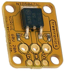
The NDRIVE can switch up to 60V and 20A of current!
You can think of the NDRIVE like an electrically controlled switch. However unlike a switch there are some things you need to consider when wiring it up.
Safety First
The NDRIVE is not suitable for switching mains level voltages.
Even though the lower voltages used with the NDRIVE are generally not high enough to deliver potentially lethal electric shocks, it is possible to miswire the NDRIVE in ways that create a lot of heat and potentially start a fire or burn you!
- Always triple-check connections for shorts and check carefully that running circuits aren't getting too hot.
- Always use thick enough wire for the current it will be carrying, and install an appropriate fuse close to the power source.
If you're not sure about safely wiring up a high-power device, find someone knowledgeable to help you.
Parts You'll Use
As well as the NDRIVE, we'll talk about the following parts of your circuit:
- Board is the Arduino-compatible Freetronics Eleven or similar board that controls the NDRIVE via a digital pin.
- Load is the high power DC powered device (a LED, lamp, motor, or similar) that you want to turn on and off using the NDRIVE. If your Load is an inductive load like a motor or a solenoid then make sure to read the section at the end of this guide
- Power Source is the source of DC voltage to drive the LOAD. Using the NDRIVE you can connect the power source to the load and turn it on and off. The power source can be any rating suitable for the load, up to 60V 20A.
Connections on the NDRIVE
- G is the "gate" connection of the MOSFET. This is a low-voltage low-current digital pin that turns the MOSFET on and off.
- D is the "drain" connection of the MOSFET. This pin connects to the Load that you want to turn on and off via the MOSFET.
- S is the "source" connection of the MOSFET. This pin connects to ground/negative terminals (on both the Power Source and the Board, all 3 points must be wired together).
Wiring up the NDRIVE
Connect the NDRIVE by wiring it like this:

- Power source positive (ie +12V or +24V, etc) wires directly to the positive side of the load.
- Drain ("D") on the module wires directly to the negative side of the load.
- Source ("S") on the module wires to the power source negative, and also the ground on the board (these must be all wired together).
- Gate ("G") on the module wires to a Digital pin on the board (any pin, whichever you want to use).
The NDRIVE has two holes, a large one and a small one, for each connection. You can use either hole depending on the wire size you are soldering to the module, or even use both if necessary.
Important: For high power loads, all of the wiring needs to be thick enough to handle high current, except for the digital output wire to the Gate.
How it works
The NDRIVE is an N-type MOSFET which is used for low-side switching. Instead of switching the power to the positive ("high") side of the Load (ie +12V or +24V, etc), the MOSFET switches power to the negative ("low") side of the Load. Current can only flow through and power the load when the negative side is connected to ground via the MOSFET.
- When the digital output is LOW, the MOSFET gate is turned off and no current can flow through the load via the MOSFET. So the load stays unpowered.
- When the digital output is HIGH, the MOSFET gate is turned on and current can flow through the load via the MOSFET Drain to the MOSFET Source. This powers the load.
Arduino Code
The Arduino code has to set the digital pin as an OUTPUT and then drive it HIGH and LOW to turn the MOSFET on and off.
The "Blink" example (find it in the Arduino IDE under File -> Examples -> Basic -> Blink) is a good test program for this. You can set the LED pin number to the pin you've connected to the NDRIVE, and the sketch will turn that output on and off every second to turn the load on and off.
If you want to use PWM to fade the output on and off then the "Fade" example (under File -> Examples -> Basic -> Fade) is also a good test program. The output will fade on and off from 0% to 100% duty cycle. If you use this approach then make sure to choose a "PWM enabled" pin on your board to connect to the Gate.
Powering the Board
Most Arduino compatible boards have an internal regulator to allow them to run on more than 5V input voltage. For example, the Freetronics Eleven can run on up to 20V DC (12V DC suggested maximum).
This means that, if suitable, you can wire the Power Source used for your high power NDRIVE circuit to the VIN pin on the board, in order to power it from the same source. Just make sure not to supply more than 5V to any of the other pins!
Warning about "inductive loads"
Inductive loads such as motors and solenoids create an "inductive spike" of "back EMF" when turning on and off. This spike can cause unexpected resets or damage to other circuits.
One way to prevent this is to use a dedicated motor driver board like the Freetronics HBridge.
Another is to attach a diode, called the "free-wheeling diode", to dissipate the spike and protect the rest of the circuits. The diode is connected as shown here:

- The cathode end of the diode (marked with a stripe) connects to the positive connection of the load.
- The anode end of the diode (no stripe) connects to the negative connection of the load.
During normal operation, no current flows through the diode. However when the load switches and an inductive spike appears, the diode will safely dissipate it.


