


by Philip Lindsay
I've never much liked to walk. If you're in the same boat then you should learn how to update your Freetronics EtherTen and Arduino Ethernet-based boards over the network. In an amazing coincidence this step-by-step guide will teach you how to do just that thanks to the wonders of a protocol called the Trivial File Transfer Protocol or TFTP.
When you've completed these steps you will be able to upload your sketch over a network to an Arduino-compatible Ethernet board. You will need to manually specify the IP address of the board and use a couple of small command-line tools to upload your sketches.
From the perspective of your Arduino the approach documented here (arduino-tftpboot) is a "push" approach - you decide when you want to update the sketch, then tell your Arduino to accept a new program (i.e. you "push" a new sketch to the Arduino). An alternate approach is a "pull" approach where your Arduino automatically checks to see if it needs to update its sketch every time it is powered on or reset (i.e. the Arduino "pulls" a new sketch from you). We do not cover the "pull" approach here: if you are interested you should check out the arduino-netboot bootloader instead.
Compatible hardware
The approach documented here should work with any combination of Arduino-compatible boards/shields that use an ATmega328 microcontroller and WIZnet network Ethernet interface. You can let us know in the Freetronics forum if you find a combination which doesn't work - patches also welcome!
This documentation has been tested with:
It is also compatible with:
-
Freetronics Eleven with Freetronics Ethernet Shield With PoE
-
Most other ATmega328 microcontroller boards/shields with Wiznet W5100 network IC. (Such as an Arduino Uno with Arduino Ethernet Shield.)
If you have an EtherMega or other non-ATmega328 board this method can in theory also work for it but we don't cover how to do so here as modifications to the bootloader are required.
Required items
-
EtherTen, Arduino Ethernet or compatible
-
An ISP Programmer -- either a standalone device such as our USBasp or a spare Arduino with the ArduinoISP sketch loaded.
-
A network that supports static IP addresses. If you want your board to acquire its IP address automatically you need a bootloader that supports DHCP. The
arduino-netbootbootloader supports DHCP but is more complex to set up and we do not document the process here.
Shoulder standing
The solution we present here (arduino-tftpboot) is based on the Perotto variation of the TFTBootloader which is itself based on the TFTBootloader release from the Arduino team. (Why did we choose the Perotto variation? Because (a) it works; and, (b) it's released.)
Freetronics has packaged up the bootloader to make it easier to install, renamed it, added a little code and documented the whole shebang. We're extremely grateful for the work done by the others and we hope our own work will help the bootloader receive wider use.
Obligatory joke
Please note: just because the protocol is called the Trivial File Transfer Protocol it's not implying the files you are transferring are trivial - just that the protocol used to transfer them is. :)
How to install and use the arduino-tftpboot bootloader
There are a number of steps you need to take to get your Arduino network-ready:
-
Install the
arduino-tftpbootbootloader platform package and libraries. -
Burn the TFTP-compatible bootloader to your Arduino.
-
Setup the configuration for your network.
-
Verify the network configuration.
-
Upload your sketch.
-
Modify your sketch to be remote-reset compatible (optional).
The first step you only need to perform once per Arduino IDE you want to use to burn the bootloader. The next three steps you will only need to do once per board you wish to make TFTP-upload compatible. The fifth step you will need to follow each time you want to change the sketch on your Arduino. The final step is only required once per sketch you want to make remote-reset compatible (so you don't have to manually reset the Arduino to receive a new sketch).
Remember, the approach we document here is the "push" option: you control when the bootloader is run and "push" a file from your computer to your Arduino.
Let's get started!
Step One: Install the arduino-tftpboot platform package
First up you need to install the "platform package" that contains the bootloader you will burn to your Arduino to make it TFTP-compatible. This also contains a library with some tools and helpful examples you can use later on.
-
Exit the Arduino application if it is running. If you don't do this the IDE won't recognise the new board package.
-
Download the
arduino-tftpbootpackage from https://github.com/freetronics/arduino-tftpboot/downloads. -
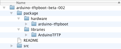
Unzip the package file. You should see the following files and folders:
-
Move the
hardwarefolder from the unzipped package into your Arduino sketchbook folder. Note: If you already have an existinghardwarefolder in your sketchbook folder then you can just move thearduino-tftpbootfolder into it instead. -
(Optional) If you want easy access to some helpful tools and examples then also move the
ArduinoTFTPfolder from thelibrariesfolder in the package into thelibrariesfolder of your Arduino sketchbook. -
When you have finished moving the folders you should see something like this in your sketchbook folder. The exact appearance will depend on what other libraries, platforms and sketches you have:

-
Start the Arduino IDE application.
-
Verify you have the platform package correctly installed by looking for a new board named
TFTP Bootloader ATmega328 (No Upload)available under theTools > Boardmenu:

If you see the new board listed then you're ready to move on to the next step. If you don't see the board listed you'll need to check you have all the folders moved to the correct place. Remember you can post to the Freetronics forum for assistance - please include as many details as you can.


Now you have the platform package installed you can burn the arduino-tftpboot bootloader onto your Arduino board. Learn how to do this in Step Two.
Step Two: Burn the bootloader
Once you have installed the TFTP-capable bootloader platform package in Step One you can burn the bootloader onto your Arduino board:
-
Select the appropriate option from the
Tools > Boardmenu:- For an EtherTen, Arduino Ethernet, Arduino Uno with Ethernet shield or other ATmega328 based board, choose:
TFTP Bootloader ATmega328 (No Upload).
- For an EtherTen, Arduino Ethernet, Arduino Uno with Ethernet shield or other ATmega328 based board, choose:
-
Connect your ISP programmer from your computer to the ISCP header pins on your Arduino or Arduino-compatible board.
-
In the
Tools > Programmermenu select the name of your programmer. e.g.USBtinyISPorArduino as ISP. -
Select the
Tools > Burn Bootloadermenu option. This will burn thearduino-tftpbootbootloader to your board. It can take around a minute for this to complete:

The IDE will display the message "Done burning bootloader." when it has finished:

-
You can confirm the bootloader has been burned successfully by connecting an LED and resistor between ground and pin 9 on your Arduino.
Immediately after the bootloader has been burned it will blink the LED at a rate of about once per second until you upload a sketch via TFTP. Once a sketch has been uploaded the LED will only blink for about three seconds after a reset/power-on (indicating the bootloader is waiting for a TFTP connection) before it stops and the uploaded sketch is executed.


You have now successfully installed the TFTP-capable bootloader on to your Arduino.
With the bootloader installed you can now decide what network configuration your Arduino will need. Our next step will help you choose the configuration you need for your network.
Step Three: Configure your network
Have you ever tried to help a friend or family member troubleshoot--over the phone--a problem they're having with their computer? It's pretty difficult--especially if you can't see what they're seeing. Trying to help you configure your network and Arduino in written documentation is a little like that.
So, we're going tell you about a few different options you have and hopefully give you enough information about when each option is appropriate that you'll be able to decide which approach is best for you. If you're still lost remember the Freetronics forum might be able to help you out with your unique situation.
By the end of this step you will know the network addresses your computer and your Arduino each need in order to be able to communicate with each other. In addition you will have stored the settings so that the arduino-tftpboot bootloader and your sketch can use them.
The default configuration
By default the arduino-tftpboot bootloader uses the following network configuration:
- IP address:
192.168.1.1 - Net mask:
255.255.255.0 - MAC address:
12:34:45:78:9A:BC - Gateway address:
192.168.1.254
If you know this configuration will work with your network you can skip the remainder of this step (lucky you!) and continue on to verify your network connection in Step Four.
If you know the default configuration won't work or you don't know if it will, you can continue to read along...
Choosing a static IP address
The arduino-tftpboot bootloader only supports a "static" IP address--it cannot use DHCP to acquire an IP address dynamically each time your Arduino is powered up.
Many networks are configured to use DHCP and if you connect a device with a static IP address to such a network it can cause problems which will make you unpopular with other people using the network.
Here are your options:
-
If you connect to your network via WiFi (most likely with a laptop) I recommend you first try to work with your Arduino directly connected to an Ethernet network port on your computer. Once you know this works properly you can then change the configuration to work with your main network. Following this approach delays being concerned about other network configuration issues until you know everything else works. See the "Direct link-local connection" section below for the simplest way to set this up.
-
If your network uses static IP addresses then you can ask the network administrator for a static IP address for your Arduino. (If your network administrator is yourself then make sure you have a well reasoned argument ready before you ask yourself.)
-
If your network uses DHCP then you either need to ask your administrator for one or more static IP addresses to be allocated or investigate using the
arduino-netbootbootloader which can use DHCP--but isn't documented here. If you are your own network administrator you can often configure your network router/DHCP server to never allocate a block of static IP address which you can then use--but how to do that configuration is outside of the scope of these instructions. -
If none of the above are possible and you are your own network administrator then you can also just set a static IP well away from the others currently in use and hope for the best. DO NOT do this without permission if you are using someone else's network because that's just plain rude.
See the "Connection via a router/switch/hub with a static IP" section below for suggestions on how to determine a suitable static IP.
Direct link-local connection
Where possible I like to make use of a link-local address as it greatly simplifies network configuration. A link-local address is an IP address that starts with 169.254.
On many operating systems when a DHCP server cannot be found on a network connection the OS will fallback to using a link-local or "self-assigned" address. For example, by default on Mac OS X when you connect a device directly to the Ethernet port this approach is used. Here is the view on Mac OS X of the Network panel of the System Preferences application when a self-assigned IP address is used:

You will notice this happens when the "Using DHCP" option is configured--when OS X cannot find a DHCP server it falls back to the link-local address instead. This means you do not need to manually set an IP address for your computer.
When using a link-local connection your Arduino needs to have an IP address which begins with 169.254. I generally cheat and use an address of 169.254.254.169 which being palindromic is easier for me to remember. If you don't suffer from this affliction then you can choose a different address in the range of 169.254.[1-254].[0-255]. The reason this is cheating is because your Arduino should check that noone else is using the same address first. But hopefully the computer you're connecting to is better behaved.
You can keep the default bootloader value for the MAC address. You will need to change the net mask to be 255.255.0.0 in order to be compatible with link-local addresses. If you want your computer to act as a "gateway" for your Arduino you'll need to set the gateway address value to match the IP address of your computer (which will be difficult if it changes each time you connect--so depending on the link-local implementation your OS uses this method is less suitable if you want your Arduino to have outgoing network access).
Once you've decided the address you want your Arduino to use you can move on to the "Storing your network settings" section below.
Connection via a router/switch/hub with a static IP
If your Arduino is to be connected to a network (via a router, switch or hub) and not directly to your computer (via a link-local connection) then you need to determine a suitable static IP:
-
If you have a network administrator then--when you request a static IP address--the administrator should provide you with the static IP address, a netmask value and the gateway address you need to use. You should ensure that you are not using the same MAC address as anyone else on your network--a clash is only likely to occur if someone else is using an Arduino on your network. If you are part of a school or other institution you should ask what the policy is for allocating a MAC address for an Arduino on the network. Armed with this information you can now move on to the "Storing your network settings" section below.
-
If you administer your own network and have determined you can use a static IP address safely then you need to work with the existing set up of your network. Most likely this means you will choose a static IP address from one of the private network address ranges: e.g.
10.x.y.z,192.168.x.yor172.16.x.y.If you're using a home network you can probably get away with looking at your own computer's IP address and then adding, say, 50 to the last digit of the address. e.g. if your computer's IP address is
10.1.1.4then try using the address10.1.1.54for your Arduino. Also, in most cases, you can probably get away with using a netmask of255.255.0.0--even if it's not strictly correct.If you want your Arduino to be able to access the internet you will need to also supply an IP address for your "internet gateway" (most likely your modem/router). Your Arduino will use the same gateway IP address that your computer does--you'll need to look at your computer's configuration to determine the correct address.
As long as you only have one Arduino on your network you can use the default bootloader MAC address. Otherwise make sure you, say, increment the last digit of the default MAC address by one for each Arduino you add to your network.
Now you too can move on to the "Storing your network settings" section below.
By now you should know the following network settings that you will use for your network connected Arduino:
- IP address
- Netmask value
- Gateway address (if you want your Arduino to access the internet)
- MAC address
Next you will learn how to store these settings so both the arduino-tftpboot bootloader installed on your Arduino and your uploaded sketches can use them.
Storing your network settings
The arduino-tftpboot bootloader has the ability to read network settings from EEPROM and use those settings rather than its defaults. First, though, you need a sketch to store the network settings in EEPROM. But once you have installed the bootloader you can't upload a sketch to it unless it has the correct settings! It ends up being a bit of a chicken-egg situation.
There is an additional complication due to the fact the default Arduino bootloader configures the Arduino so the EEPROM is erased when a bootloader or sketch is uploaded via an ISP programmer. This means the settings in EEPROM will not be preserved if we write network settings to EEPROM from a sketch before we install the new bootloader.
The solution (if you can't use the default bootloader network settings) is to:
-
Burn the
arduino-tftpbootbootloader (as you did in Step Two). -
Write the network settings to EEPROM with the
WriteNetworkSettingssketch (which you're about to do). -
Burn the
arduino-tftpbootbootloader (again).
The way this works is that the first time you burn the bootloader it also configures your Arduino to preserve the contents of the EEPROM whenever you next burn a bootloader or sketch. But when you upload the network settings sketch via the programmer it also overwrites the bootloader. So, then you have to burn the bootloader again but this time it will preserve and use the settings in EEPROM. (Yes, it's frustrating repetition but it seems there is no easier way.)
Here's how to write the network settings:
-
Open the
File > Examples > ArduinoFTP > WriteNetworkSettingssketch. -
Modify the gateway/netmask/IP/MAC details in the
NetworkSettingssection of the file, as required, using the values you chose in the "Choosing a static IP address" section of this step. (The comments at the head of the file provide two other settings variations you can use via copy & paste.) -
Upload the sketch via your ISP programmer.
-
Let the sketch run once. When the sketch has finished an LED attached to Pin 9 will blink rapidly.
-
(Optional) If you have a serial connection to your Arduino board you can check that the EEPROM has the correct values by uploading the
eeprom_readsketch via your ISP programmer (File > Examples > EEPROM > eeprom_read) and verifying the values it prints to the serial monitor. The output should look something like this:0 85 1 170 2 255 3 10 4 1 5 1 6 1 7 255 8 0 9 0 10 0 11 18 12 52 13 69 14 120 15 154 16 188 17 10 18 1 19 1 20 20
Now that you have the network settings stored you need to go back and repeat Step Two to burn the arduino-tftpboot bootloader back onto your Arduino.
Do that now.
Once the arduino-tftpboot bootloader is installed on your Arduino again you will need to verify your Arduino's network settings and then you can upload a sketch over the network. You'll learn how to do this in steps four and five, which are coming up right about....now.
Step Four: Verify the network connection
Before you upload your first sketch over the network you need to confirm that the network settings for the Arduino, bootloader and your computer are correct. Let's do that now!
Connect power
You will need to use a "wall wart" or similar power adapter to supply power to your Arduino board - connect that now. If you are using a switch - or injector - that provides Power-over-Ethernet you will not need a separate power supply. For testing purposes you can also use the power from the USB connector or programmer.
Connect a network cable
If you intend to connect your Ethernet-capable Arduino directly to your computer (which you will do if you're using a link-local connection) then you can use an Ethernet cable to connect from your computer's Ethernet port to the Ethernet port on your Arduino. The Ethernet chip on the Arduino (and in most computers) is smart enough to work out there's a computer on the other end so there's no need to use a special "cross-over" cable).
If you intend to connect your Arduino to a router, switch or hub then you can use an Ethernet cable to connect from a Ethernet port on the router/switch/hub to the Ethernet port on your Arduino.
When you connect the Ethernet cable, one of the LEDs on the Ethernet connector on the Arduino board should be lit steadily to indicate a "link" has been established to the router/switch/computer while the other LED should blink to indicate traffic on the connection. (On an EtherTen the green LED shows the "link" is connected, while the orange LED represents "traffic" on the link. The colours may be different on other boards.)
Test the connection
To check that the bootloader has been correctly configured you can use the ping utility that comes with your computer.
Start a Terminal, shell or command line session (the name differs on each operating system) and instruct your computer to contact your Arduino with (by default):
ping 192.168.1.1
(If you have used the WriteNetworkSettings to change the IP address of the Arduino you should use that address instead.)
You should see a response like:
    PING 192.168.1.1 (192.168.1.1): 56 data bytes
    64 bytes from 192.168.1.1: icmp_seq=0 ttl=128 time=0.180 ms
    64 bytes from 192.168.1.1: icmp_seq=1 ttl=128 time=0.126 ms
    64 bytes from 192.168.1.1: icmp_seq=2 ttl=128 time=0.191 ms
You can use Ctrl-C (or Control-C) to interrupt the ping command when you want to stop the response or if the display shows no response other than something like this after a few seconds:
PING 192.168.1.1 (192.168.1.1): 56 data bytes
If you get no response from your Arduino (i.e. no lines of text with the bytes from words in them) check the following:
-
Does your Arduino have power? (Is the power light on?)
-
Is your Arduino plugged firmly into your computer or network switch with an Ethernet cable? (Are the link and activity lights lit and/or blinking?)
-
Is the IP address of your computer on the same network as your Arduino? (Do both addresses start with
192.168or10.or169.254?) -
Is the correct bootloader (i.e.
arduino-tftpboot) installed on your Arduino? -
Does a different cable, computer, switch, Arduino board or power source make a difference?
-
If you're still having problems try posting on the Freetronics forum. Include as much detail about your set up as you can.
Hopefully you will have received a ping response and can move onto to the next step and finally upload a sketch over the network!
Step Five: Upload your sketch
Unfortunately uploading over the network is not yet directly supported by the Arduino IDE so it takes a few more steps than usual.
Enable verbose compilation output
While the Arduino IDE will compile our sketch for us as normal, we need to know where the IDE puts the compiled file. To do this we need to enable "verbose compilation output":
-
Open the Arduino
Preferencesdialog. (Arduino 1.0 or later.) -
Ensure the compilation option is selected for Show verbose output during:

-
Click
OK.

You only need to set this once.
Compile a sketch
-
Ensure the correct board is selected (as you did previously in Step Two):
- For an EtherTen, Arduino Ethernet, Arduino Uno with Ethernet shield or other ATmega328 based board, choose:
TFTP Bootloader ATmega328 (No Upload).
- For an EtherTen, Arduino Ethernet, Arduino Uno with Ethernet shield or other ATmega328 based board, choose:
-
If you have connected an LED an resistor to pin 9 you can open the
File > Examples > ArduinoTFTP > BlinkUploadTestsketch. (Otherwise you'll need to choose a different sketch with which to test.) -
Click the
Verifybutton, choose theSketch > Verify / Compilemenu option or use the associated keyboard shortcut. -
Wait until the compile completes with a message like this:

-
Note the text on the third to last line (highlighted in the screenshot above) of the output that ends with
BlinkUploadTest.cpp.elf. Copy this line of text (you can select it in the output and copy as normal) to a temporary location. This line of text is the file path of the compiled version of your sketch.(Ensure you don't copy the line that ends with
.hex. Also, depending on the width of your editor window the file path may not be on a line on its own--yeah, helpful I know. You'll find it.)The file path will mostly contain a jumble of characters (it depends on your operating system and isn't important) but must end with the name of your sketch plus
cpp.elf:/var/folders/Tz/TzIfZ5NdGlqu4eNpoUSLDE+++TI/-Tmp-/build1676179778849833945.tmp/BlinkUploadTest.cpp.elfYou will use this file path when you convert the compiled sketch into a form the bootloader can understand, which you will do next...

Convert sketch for bootloader
Due to the way the bootloader works we need to convert from the compiled file format the Arduino IDE produces to a format the bootloader can understand.
The conversion uses the avr-objcopy tool from the avr-gcc package--this is distributed with the Arduino IDE on Windows & Mac OS X but needs to be installed separately on Linux distributions. avr-gcc may also be installed separately on Windows or Mac OS X but in most cases it's best to use the version that ships with the IDE.
-
Start a Terminal, shell or command line session (depending on your operating system).
-
Check if you can use
avr-objcopythe easy way by typing the following:avr-objcopyIf you get an error message then you'll need to try the more convoluted way:
-
For Mac OS X:
-
If you have installed the Arduino application for yourself this will probably work:
~/Applications/Arduino.app/Contents/Resources/Java/hardware/tools/avr/bin/avr-objcopy -
If someone else installed the Arduino application for you and the above does not work, try:
/Applications/Arduino.app/Contents/Resources/Java/hardware/tools/avr/bin/avr-objcopy -
If none of these works you'll need to find where the
Arduino.appfile is on your computer and use the path to it instead.
-
-
For Windows:
-
Find the location of the directory with the
arduino.exefile in it (it will likely be namedarduino-1.0.1or similar). -
Type the following in the command window, replacing
<path>with the full path to the directory you found:<path>\arduino-1.0.1\hardware\tools\avr\bin\avr-objcopy.exe
-
-
For Linux:
-
Ensure the
avr-gccpackage is installed (if should be if the Arduino IDE compiles sketches successfully). -
Realise that typing
avr-objcopyshould just work.
For the remaining instructions wherever you see
avr-objcopyuse the way that works for you as you discovered above. -
-
-
Now, type the following using the file path to the compiled sketch you found in the last part of the "Compile a sketch" section above:
avr-objcopy -j .text -j .data -O binary /var/folders/Tz/TzIfZ5NdGlqu4eNpoUSLDE+++TI/-Tmp-/build487380010353079610.tmp/BlinkUploadTest.cpp.elf BlinkUploadTest.binThis command extracts the required parts from the compiled sketch and saves it in the form the bootloader understands. The saved file is named
BlinkUploadTest.binand will be in the current directory of your shell (so you may wish to change directory before running the command).
Upload the sketch
To upload the sketch we use another command line tool, funnily enough it's named tftp.
As you might expect tftp on each operating system works a little differently, so when the instructions below say "start the sketch binary file upload" this is what you will need to do:
-
For Mac OS X:
A simple
tftpprogram is installed by default on OS X.-
Open a Terminal window.
-
Ensure you are in the same directory as the
BlinkUploadTest.binfile you created earlier. (This is required becausetftpon OS X does not appear to support directories when specifying the name of the file to upload.) -
Start the tool with:
tftp -e <Arduino IP address>e.g. if your Arduino has the default
192.168.1.1address, use:tftp -e 192.168.1.1The
-eswitch indicates you want to send the file inbinaryform.When the tool starts you will see a prompt like:
tftp>Unfortunately the file you want to upload can't be specified on the command line so you will need to supply that separately, next.
-
Type the following at the prompt:
put BlinkUploadTest.bin -
Once the file has uploaded you can exit the tool with:
quit
-
-
For Windows:
A
tftpprogram is installed by default on Windows XP. Later versions may require you to enable the tool first.-
Open a console command line window.
-
Perform the upload by typing:
tftp -i <Arduino IP address> put <filename>.bine.g. if your Arduino has the default
192.168.1.1address, use:tftp -i 192.168.1.1 put BlinkUploadTest.binThe
-iswitch indicates you want to send the file inbinaryform.
-
-
For Linux:
Your distribution may or may not ship with a
tftptool installed by default. Iftftpis not installed you'll need to use your package manager or other tool to install it.Once you have a
tftptool installed do the following:-
Open a shell window.
-
Perform the upload by typing:
tftp -mode binary <Arduino IP address> -c put <filename>.bine.g. if your Arduino has the default
192.168.1.1address, type:tftp -mode binary 192.168.1.1 -c put BlinkUploadTest.bin
-
And here's the whole process to upload the sketch:
-
Ensure your Arduino is powered up.
-
Ensure your Arduino is connected to the network. (As per Step Four above.)
-
Start the sketch binary file upload (as per the instructions for your operating system above).
-
Press the reset button on your Arduino board.
-
When the transfer has completed the
tftpcommand should display a message like (from OS X):Sent 1084 bytes in 0.3 secondsWith this test sketch you should also be able to see a LED attached to pin 9 blinking once per second.
-
If you get an error:
-
Try the upload process again--the timing of the upload/reset process can be important.
-
Try pressing reset before you start the sketch binary file upload.
-
Ensure network connectivity as per Step Four above.
-
Confirm you have the correct bootloader burned on the board.
-
If you're still having problems try posting on the Freetronics forum. Include as much detail about your set up as you can.
-
(Note: The first time you try to upload after burning the bootloader you don't actually need to press the reset button--the bootloader just sits in a loop waiting for the first sketch to be uploaded. On subsequent resets the bootloader only waits a few seconds before running the existing sketch.)
Now you have confirmed the network upload process works you can optionally also test network functionality in the sketch itself.
Test a sketch that uses the network
Unless you just want to use the network to upload sketches (which seems unlikely) then you will also want to check that an uploaded sketch can use the network itself.
The key issue is that the bootloader and your sketch need to be consistent with their use of MAC address and IP address. For example, if the bootloader uses a particular IP address and your sketch uses the same IP address but a different MAC address things will probably grind to a halt. (You can verify this by pinging your Arduino and if it responds while in the bootloader but not when your sketch is running that may be why.)
Ideally there would be a library function that can automatically configure your sketch with the same settings as the bootloader but such a thing has not been written (feel free to contribute something). In the interim there is a modified version of the standard Ethernet library's WebServer example sketch which you can use that includes a function to read the IP address from EEPROM.
-
Open the
File > Examples > ArduinoTFTP > WebServerWithSettingssketch. -
Compile & upload the sketch--ensure the MAC address in the sketch is the same as used by the bootloader.
-
In a web browser visit the IP address of your Arduino. The standard demonstration page should appear.
If you want to add this functionality to your own sketches, you'll need to add the following code:
-
Replace your current MAC address and IP address configuration variable declarations with:
    // Enter a MAC address for your controller below--it must match the one the bootloader uses.
    byte mac[] = {0x12,0x34,0x45,0x78,0x9A,0xBC};
// The IP address will be read from EEPROM or be set to a value default in `configureNetwork()`. IPAddress ip; -
Add the following function:
    void configureNetwork() {
      // Reads IP address from EEPROM as stored by `WriteNetworkSettings` sketch.
#define EEPROM_SIG_1_VALUE 0x55 #define EEPROM_SIG_2_VALUE 0xAA #define EEPROM_SIG_1_OFFSET 0 #define EEPROM_SIG_2_OFFSET 1 #define EEPROM_GATEWAY_OFFSET 3 #define EEPROM_MASK_OFFSET 7 #define EEPROM_MAC_OFFSET 11 #define EEPROM_IP_OFFSET 17 if ((EEPROM.read(EEPROM_SIG_1_OFFSET) == EEPROM_SIG_1_VALUE) && (EEPROM.read(EEPROM_SIG_2_OFFSET) == EEPROM_SIG_2_VALUE)) { ip = IPAddress(EEPROM.read(EEPROM_IP_OFFSET), EEPROM.read(EEPROM_IP_OFFSET+1), EEPROM.read(EEPROM_IP_OFFSET+2), EEPROM.read(EEPROM_IP_OFFSET+3)); } else { ip = IPAddress(192,168,1,1); }; // TODO: Handle MAC, mask & gateway also. } -
In the
setup()function add theconfigureNetwork()call before theEthernet.begin()call, like this:configureNetwork();// start the Ethernet connection and the server: Ethernet.begin(mac, ip);Your sketch will now read its IP address from EEPROM as the bootloader does.
You've now got everything you need to upload your network-capable sketches over the network!
But wait, I hear you say, "I was promised I wouldn't have to walk anywhere"...
Read on, lazy reader, read on...
Step Six: Remote reset (Optional)
Once you can upload a sketch over the network you may start to think you also need a way to remotely reset the Arduino so you don't need to walk over to the board to press the onboard reset button. We need to reset the Arduino in order to start the bootloader so it is ready to receive the sketch over the network.
An Arduino has what's known as a watchdog which monitors whether or not it is operating in a correct manner. If the watchdog has detected the Arduino has hung (i.e. it's unresponsive) it will reset the Arduino into the bootloader. We can use this functionality to trigger the reset remotely--by intentionally "hanging" the Arduino.
-
Open the
File > Examples > ArduinoTFTP > WebServerWithResetsketch. -
Compile & upload the sketch--ensure the MAC address in the sketch is the same as used by the bootloader.
-
In a web browser visit the IP address of your Arduino. The standard demonstration page should appear.
-
Compile a new sketch (e.g. edit the
WebServerWithResetsketch to change the output) and then start the sketch binary file upload with thetftptool. -
In a web browser visit the IP address of your Arduino but specify port
81rather than the default port, e.g.:http://192.168.1.1:81/(If you prefer you can also use a tool like
curl,wgetortelnetto perform the same task. It must connect to port 81 and send one byte of arbitrary data to trigger the reset.) -
Your web browser will display an error message but in a couple of seconds your Arduino will reset and the bootloader will be active for a few seconds.
-
Once the bootloader is active it should start to receive the new sketch and then run it.
-
(If you edited the
WebServerWithResetsketch, view the changed output by visiting the IP address of the Arduino in a browser as usual.) -
Look Ma, no feet!
While remote reset is great you should note:
-
It's possible for your sketch to malfunction in such a way that you cannot connect to it over the network to force a reset--so don't put your project in a box, throw away the key and have no way to reset your Arduino manually.
-
There's no security associated with the remote reset--anyone else on your network can trigger a reset and potentially upload their own sketch (accidentally or intentionally). It would be unwise to enable remote reset on a device that is connected to a public network.
To add the remote reset functionality to your own sketches add the following code:
-
At the beginning of your sketch:
#include <avr/wdt.h> -
Before the
setup()function:// Connections to this port will cause a reset to the bootloader // so a sketch can be uploaded. EthernetServer reset_server(81); -
At the beginning of your
loop()function:// Check for a connection that indicates we should reset to the bootloader // so another sketch can be uploaded. // Note: This approach means that if the sketch hangs later in the loop then any connection // attempt will not be detected so reset will not occur. So, don't hang. :) EthernetClient reset_client = reset_server.available(); // Unfortunately requires a byte sent.if (reset_client) { reset_client.stop(); wdt_disable(); wdt_enable(WDTO_2S); while (1); }
And that's it! Have fun!
Thanks for following along with this tutorial. If you have suggestions on how we can improve the tutorial or you want to show us your cool TFTP-enabled projects please leave a message on our forum, send us an email or contact us on Twitter @freetronics.


