


The H-Bridge Motor Driver Shield gives your Arduino the ability to drive DC motors and stepper motors, between 8V and a maximum of 40V / 2A peak.
The two output channels can be used independently to control two DC motors, or they can be combined to control a single 4-wire stepper motor.

Warning: The Allegro A4954 motor controller chip used on this shield is rated to operate at up to 160C. Do not be alarmed if the board runs very hot during operation, and do not touch the controller chip when it has been in use. It can easily become hot enough to burn you. Good ventilation or active cooling may be necessary in some applications, depending on motor type, load, and supply voltage.
Controlling A 4-Wire Bipolar Stepper Motor
Stepper Hardware Setup
1. Fit the H-Bridge Motor Driver Shield to your Arduino. The shield includes extended “R3” headers, but it is also compatible with older Arduino models without the new SCL, SDA, and IOREF pins. If you do not need these pins you can cut them off if they get in the way, as they are not used by the shield.
2. Optionally connect an external DC power supply to the screw terminals marked “Motor Power In Max 40Vdc”. The power supply should be a voltage suitable for your stepper motor.
3. Optionally fit the jumper to the header marked “Bridge VIN To Motor Power”. This header links your Arduino's VIN pin to the motor power supply on the shield, allowing you to either power your Arduino using the motor power supply, or power the motors from your Arduino's DC jack. You cannot power the motor shield with only USB power. Be sure you don't exceed the maximum input voltage rating for your Arduino.
4. Connect a 4-wire stepper motor to outputs 1 through 4, according to the specifications provided by your stepper motor manufacturer. Bipolar stepper motors have 2 coils internally, with one pair of wires per coil. Connect one pair to output channel A, and the other pair to output channel B.
5. Ensure jumpers are in place across the pairs of pins labelled Channel A and Channel B. These jumpers connect the H-bridge controller IC to digital pins on your Arduino, allowing your sketch to control the motor controller.
6. Set the current limit to 0.6A, 1.2A, or 2A for each channel using the switches on the shield.

The photo above shows a bipolar stepper with one coil on red/green, and the other coil on yellow/blue. The jumper is in place on the shield to link VIN to motor power, and a 12V power source is connected to the Arduino's DC jack to provide power to VIN. Alternatively, power could be supplied through the motor input screw terminals on the shield.
Example Stepper Sketch
The following example sketch uses the "stepper" library included in the Arduino IDE, and is based on the example found at File -> Examples -> Stepper -> stepper_oneRevolution, with minor changes to suit the pinouts on the HBridge Shield.
/*
 Based on example by Tom Igoe included in Arduino IDE
 at File -> Examples -> Stepper -> stepper_oneRevolution

 Modified to suit pinouts of Freetronics HBridge Shield
*/

#include <Stepper.h>

const int stepsPerRevolution = 240;  // change this to fit the number of steps per revolution
                                     // for your motor

// initialize the stepper library using the default pins on the HBridge Shield:
Stepper myStepper(stepsPerRevolution, 4, 7, 3, 2);

void setup() {
  // set the speed at 200 rpm:
  myStepper.setSpeed(200);
  // initialize the serial port:
  Serial.begin(9600);
}

void loop() {
  // step one revolution  in one direction:
   Serial.println("clockwise");
  myStepper.step(stepsPerRevolution);
  delay(1000);

   // step one revolution in the other direction:
  Serial.println("counterclockwise");
  myStepper.step(-stepsPerRevolution);
  delay(1000);
}
When running this sketch you may notice that the stepper motor continues to make noise and strongly hold its position during the 1-second pause between rotations. This is because the driver chip applies a "brake" function to hold the motor at the last position it was placed. You can use the "enable" lines to control this behaviour by disabling the output channels when the motor is not being driven, as shown in this expanded example:
/*
 Based on example by Tom Igoe included in Arduino IDE
 at File -> Examples -> Stepper -> stepper_oneRevolution

 Modified to suit pinouts of Freetronics HBridge Shield
*/

#include <Stepper.h>

const int stepsPerRevolution = 240;  // change this to fit the number of steps per revolution
                                     // for your motor

const int enableA = 6;
const int enableB = 5;

// initialize the stepper library using the default pins on the HBridge Shield:
Stepper myStepper(stepsPerRevolution, 4, 7, 3, 2);

void setup() {
  // set up the enable pins:
  pinMode(enableA, OUTPUT);
  pinMode(enableB, OUTPUT);
  // set the speed at 200 rpm:
  myStepper.setSpeed(200);
  // initialize the serial port:
  Serial.begin(9600);
}

void loop() {
  // step one revolution in one direction:
  Serial.println("clockwise");
  digitalWrite(enableA, HIGH);
  digitalWrite(enableB, HIGH);
  myStepper.step(stepsPerRevolution);
  digitalWrite(enableA, LOW);
  digitalWrite(enableB, LOW);
  delay(1000);

  // step one revolution in the other direction:
  Serial.println("counterclockwise");
  digitalWrite(enableA, HIGH);
  digitalWrite(enableB, HIGH);
  myStepper.step(-stepsPerRevolution);
  digitalWrite(enableA, LOW);
  digitalWrite(enableB, LOW);
  delay(1000);
}
Controlling A 2-Wire DC Motor
You can control one or two DC motors using the two output channels on the shield.
DC Motor Hardware Setup
1. Fit the H-Bridge Motor Driver Shield to your Arduino. The shield includes extended “R3” headers, but it is also compatible with older Arduino models without the new SCL, SDA, and IOREF pins. If you do not need these pins you can cut them off if they get in the way, as they are not used by the shield.
2. Optionally connect an external DC power supply to the screw terminals marked “Motor Power In Max 40Vdc”. The power supply should be a voltage suitable for your DC motor.
3. Optionally fit the jumper to the header marked “Bridge VIN To Motor Power”. This header links your Arduino's VIN pin to the motor power supply on the shield, allowing you to either power your Arduino using the motor power supply, or power the motors from your Arduino's DC jack. You cannot power the motor shield with only USB power. Be sure you don't exceed the maximum input voltage rating for your Arduino.
4. Connect a 2-wire DC motor to either channel A using outputs 1 and 2, or to channel B using outputs 3 and 4.
5. Ensure jumpers are in place across the pairs of pins labelled Channel A and Channel B. These jumpers connect the H-bridge controller IC to digital pins on your Arduino, allowing your sketch to control the motor controller.
6. Set the current limit to 0.6A, 1.2A, or 2A for each channel using the switches on the shield.
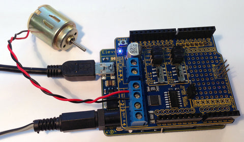
The photo above shows a DC motor connected to channel A. The jumper is in place on the shield to link VIN to motor power, and a power source is connected to the Arduino's DC jack to provide power to VIN. Alternatively, power could be supplied through the motor input screw terminals on the shield. A second motor could also be connected to channel B.
Example DC Motor Sketch
This example sketch includes definitions for the control pins for both output channels, but only drives channel A. You can alter it to suit your own requirements.
const int channel_a_enable  = 6;
const int channel_a_input_1 = 4;
const int channel_a_input_2 = 7;
const int channel_b_enable  = 5;
const int channel_b_input_3 = 3;
const int channel_b_input_4 = 2;

void setup()
{
  pinMode( channel_a_enable, OUTPUT );  // Channel A enable
  pinMode( channel_a_input_1, OUTPUT ); // Channel A input 1
  pinMode( channel_a_input_2, OUTPUT ); // Channel A input 2

  pinMode( channel_b_enable, OUTPUT );  // Channel B enable
  pinMode( channel_b_input_3, OUTPUT ); // Channel B input 3
  pinMode( channel_b_input_4, OUTPUT ); // Channel B input 4

  Serial.begin( 9600 );
  Serial.println("Starting up");
}

void loop()
{
      Serial.println("Channel A forward");
      analogWrite( channel_a_enable, 255);
      digitalWrite( channel_a_input_1, HIGH);
      digitalWrite( channel_a_input_2, LOW);
      delay(5000);
      allInputsOff();

      Serial.println("Channel A reverse");
      analogWrite( channel_a_enable, 255);
      digitalWrite( channel_a_input_1, LOW);
      digitalWrite( channel_a_input_2, HIGH);
      delay(5000);
      allInputsOff();

      Serial.println("Channel A forward half speed");
      analogWrite( channel_a_enable, 127);
      digitalWrite( channel_a_input_1, HIGH);
      digitalWrite( channel_a_input_2, LOW);
      delay(5000);
      allInputsOff();
}

void allInputsOff()
{
  digitalWrite( 4, LOW );
  digitalWrite( 7, LOW );
  digitalWrite( 6, LOW );
  digitalWrite( 3, LOW );
  digitalWrite( 2, LOW );
  digitalWrite( 5, LOW );
}
You can see in the sketch that to make a motor run in one direction, one of the inputs for that channel is set to LOW and the other is set to HIGH. Reversing the levels of the inputs also reverses the direction of the motor. The "enable" line can then be used to control the speed of the motor using PWM, with a value of 0 being off, and 255 being full on.
Note that using this technique you can drive motors at higher than their rated voltage. For example, you could drive a 12V DC motor with an 18V source, as long as you modulate the "enable" input so that it is not set to full on.


