


This is a guide to using the Freetronics FreeNFET Addressable N-MOSFET Module to switch large loads on and off from your Arduino-compatible board.
Why do you need FreeNFET?
The output pins on an Arduino-compatible board are limited:
- They can't tolerate voltages higher than 5V (3.3V for some boards).
- They can't supply more than 20mA of current (less on some boards).
If you have a high power device like a large LED, lamp or motor that requires more than 5V of voltage or more than 20mA of current to drive, you will need additional circuitry to switch it on and off. A MOSFET is one way to do this. The FreeNFET Addressable N-MOSFET Module provides a MOSFET in an easy to connect module format, with an onboard driver IC that allows multiple modules to be controlled from a single I/O pin:

The FreeNFET can switch up to 60V and 18A of current!
You can think of the FreeNFET like an electrically controlled switch. However unlike a switch there are some things you need to consider when wiring it up.
Safety first
The FreeNFET is not suitable for switching mains level voltages.
Even though the lower voltages used with the FreeNFET are generally not high enough to deliver potentially lethal electric shocks, it is possible to miswire the FreeNFET in ways that create a lot of heat and potentially start a fire or burn you!
- Always triple-check connections for shorts and check carefully that running circuits aren't getting too hot.
- Always use thick enough wire for the current it will be carrying, and install an appropriate fuse close to the power source.
If you're not sure about safely wiring up a high-power device, find someone knowledgeable to help you.
Parts you'll use
As well as the FreeNFET, we'll talk about the following parts of your circuit:
- Board is the Arduino-compatible Freetronics Eleven or similar board that controls the FreeNFET via a digital pin.
- Load is the high power DC powered device (a LED, lamp, motor, or similar) that you want to turn on and off using the FreeNFET. If your load is an inductive load like a motor or a solenoid then make sure to read the section at the end of this guide
- Power Source is the source of DC voltage to drive the load. Using the FreeNFET you can connect the power source to the load and turn it on and off. The power source can be any rating suitable for the load, up to 60V 18A.
Connections on the FreeNFET
- VCC supplies power to the controller IC. This is a low-voltage low-current digital pin that is typically connected to the 5V header of your Arduino.
- GND is the ground connection of the module. Connect to the GND header of your Arduino.
- DI is the "data input" connection to the module. This is a low-voltage low-current digital pin that sends commands to the module.
- DO is the "data output" connection from the module. This is a low-voltage low-current digital pin that passes commands through to the next module in a chain.
- D is the "drain" connection of the N-MOSFET on the module. This pin connects to the load that you want to turn on and off via the MOSFET.
- S is the "source" connection of the N-MOSFET on the module. This pin connects to ground/negative terminals. This is connected on the module to GND, so it effectively ties the power supply GND and the Arduino GND together.
Wiring up the FreeNFET
Connect the FreeNFET by wiring it like this:
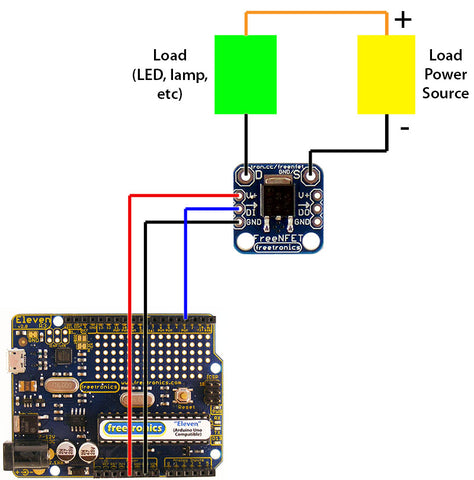
- Power source positive (ie +12V or +24V, etc) wires directly to the positive side of the load.
- Drain ("D") on the module wires directly to the negative side of the load.
- Source ("S") on the module wires to the power source negative, and also the ground on the module.
- VCC on the module wires to a 5V pin on the Arduino.
- GND on the module wires to a GND pin on the Arduino.
- DI on the module wires to a digital pin on Arduino. This can be any pin, whichever you want to use. We've used pin 3 in this example.
Important: For high power loads, all of the load wiring needs to be thick enough to handle high current. The low-power connections between the module and the Arduino can be lightweight wire because they don't carry much power.
How it works
The FreeNFET includes an N-type MOSFET which is used for low-side switching. Instead of switching the power to the positive ("high") side of the Load (ie +12V or +24V, etc), the MOSFET switches power to the negative ("low") side of the Load. Current can only flow through and power the load when the negative side is connected to ground via the MOSFET.
- When the MOSFET gate is turned off, no current can flow through the load via the MOSFET. So the load stays unpowered.
- When the MOSFET gate is turned on, current can flow through the load via the MOSFET Drain to the MOSFET Source. This powers the load.
Arduino code
The FreeNFET module includes a WS2811 driver IC, so you can control it using libraries or code that are compatible with that IC. The N-MOSFET on the module is controlled by the red channel of the WS2811 driver IC. By controlling the red output you can control the state of the MOSFET.
Compatible software includes the FastLED library and the NeoPixel library. We'll use the FastLED library.
Go to FastLED.io and follow the instructions to download and install the library. Then restart the Arduino IDE.
In the Arduino IDE, select "File -> Examples -> FastLED -> Blink".
Line 9 of the Blink example specifies the DATA_PIN setting, which is the digital pin used to communicate with the module. The example uses pin 3, but you can change it to suit your project.
Line 10 specifies the CLOCK_PIN setting, but we don't care about that. You can leave it unchanged, or even comment it out.
Line 23 specifies the device type as a NEOPIXEL. You can leave that unchanged if you like: it will work with the FreeNFET, but the colour channels are ordered differently so you'll need to control the green channel instead of the red channel. For now, comment out that line by putting two slashes in front of it.
Line 20 specifies the device type as a WS2811. This is the controller IC used on the FreeNFET, so uncomment this line by removing the two slashes in front of it.
Now you're ready to go. The last part of the sketch flashes the red channel on and off at half second intervals, so if you run the sketch now it will turn the MOSFET full-on and full-off.
You can also use PWM (pulse width modulation) which can be useful if you want to control the brightness of a high-power LED or other load. The red channel can be set to a value between 0 (off) and 255 (full on).
Powering the board
Most Arduino compatible boards have an internal regulator to allow them to run on more than 5V input voltage. For example, the Freetronics Eleven can run on up to 20V DC (12V DC suggested maximum).
This means that, if suitable, you can wire the Power Source used for your high power circuit to the VIN pin on the board, in order to power it from the same source. Just make sure not to supply more than 5V to any of the other pins!
Daisy-chaining multiple modules
Because the module is addressable, you can connect multiple modules together and control their outputs independently. The modules have handy pass-through connections so that you can chain them together like this:

They can then be controlled just like a string of addressable LEDs. See the example code included with the libraries mentioned above to see how to control multiple modules.
Warning about "inductive loads"
Inductive loads such as motors and solenoids create an "inductive spike" of "back EMF" when turning on and off. This spike can cause unexpected resets or damage to other circuits.
One way to prevent this is to use a dedicated motor driver board like the Freetronics Bridge Shield.
Another is to attach a diode, called the "free-wheeling diode", to dissipate the spike and protect the rest of the circuits. The diode is connected as shown below. This diagram uses an NDRIVE module as the example, but it works exactly the same when connecting an inductive load to a FreeNFET:

- The cathode end of the diode (marked with a stripe) connects to the positive connection of the load.
- The anode end of the diode (no stripe) connects to the negative connection of the load.
During normal operation, no current flows through the diode. However when the load switches and an inductive spike appears, the diode will safely dissipate it.


