


The 8-Channel Relay Driver Shield makes it simple and convenient to drive up to 8 loads such as 12V relays from just 2 pins of your Arduino compatible board or other microcontroller. You can use any of the output channels independently, so simply leave any unused channels disconnected.
The shield uses Arduino analog pins A4 and A5 for "I2C" serial communications with your sketch. No other pins on the Arduino are used by the shield other than power, so they are all available for connection to other devices in your projects.
Shield Connections
Mount the 8-Channel Relay Driver Shield on your Arduino-compatible board. Connect from 1 to 8 channels to your relays as required. Relays are connected directly to each output channel. In many tutorials about relays you will see instructions that you must include a protection diode across the relay terminals. You do not need to do that when using the 8-Channel Relay Driver Shield, because the protection diodes are built in to the shield itself.

INPUT 5-24 Vdc +: Connect to the positive (+) lead of the power source for your relays. Can be 5 to 24V DC.
INPUT 5-24 Vdc -: Connect to the negative (-) lead of the power source for your relays.
Relay 1 +: Connect to the + side of the coil of your first relay.
Relay 1 -: Connect to the - side of the coil of your first relay.
Relay 2-8 +: As per Relay 1 +.
Relay 2-8 -: As per Relay 1 -.
Relay Power Supply Options
There are several options for supplying power to the relays connected to the shield, depending on the settings of the jumper labelled "POWER INPUT CONNECT TO VIN" and where you connect your power supply.
Option 1: Separate power supply. This is the method recommended for most applications. In this option the power supply for the Arduino and the power supply for the relays are kept separate, so you need two power supplies: one for the Arduino, one for the relays. Leave the jumper labelled "POWER INPUT CONNECT TO VIN" off the board, and connect an appropriate DC power supply to suit your relays using the screw terminals marked "INPUT 5-24Vdc". The negative ("-") power supply connection is linked to GND on the Arduino to provide a common 0V reference, and the positive ("+") power supply connection goes to the relays.
Option 2: Pass power from relay supply to Arduino. In this option the power source used to supply the relays is also used to supply the Arduino. Place the jumper labelled "POWER INPUT CONNECT TO VIN", and connect an appropriate DC power supply to suit your relays using the screw terminals marked "INPUT 5-24Vdc". Any power you apply to the screw terminals will then be automatically sent through to the VIN input on the Arduino so that its onboard power supply can regulate it to 5V. Note that with this option you must be careful to use a power supply that matches the limits of the Arduino, so a supply of around 7V to 9Vdc is recommended. You do not need any power supply connected directly to your Arduino.
Option 3: Pass power from Arduino power supply to relays. In this option the power source used to run your Arduino is also used to power the relays. Place the jumper labelled "POWER INPUT CONNECT TO VIN", and connect an appropriate power supply to your Arduino. Any power you apply to your Arduino will then be automatically sent through to the relays connected to the shield. You do not need any power supply connected to the screw terminals on the shield.
If you are using a Freetronics EtherMega board - you must apply power to the shield via the terminal block. Furthermore, the I2C pins are located at D20 (SDA) and D21 (SCL) - not A4 and A5. If you're only going to use your shield with a Mega-style board, snip off the A4 and A5 pins from the shield and run jumper wires over from shield A4 to D20 and shield A5 to D21. If you don't want to modify your board, just bend the pins out so they don't slot into the 'Mega A4/A5 sockets.
I2C Address Jumpers
The I2C communications bus used to control the 8-Channel Relay Driver Shield allows multiple devices to share the same connections. Each device requires its own address, which is set using jumpers fitted to the positions labelled "I2C ADDR". The address lines 0, 1, and 2 are held LOW, or logical 0, by default on the shield. Fitting a jumper in any position will set the matching address line HIGH, or logical 1.
When communicating with the shield, your sketch must specify the I2C address of the particular shield it wants to talk to. With all jumpers removed (the default) the address is 0x20. All possible addresses are shown in the table below. "0" shows the jumper is off, "1" shows the jumper is on. Up to eight 8-Channel Relay Driver Shields can be stacked and addressed independently, giving you up to 64 relay output channels using only two pins on your Arduino.
| Addr 0 | Addr 1 | Addr 2 | Shield Address |
| 0 | 0 | 0 | 0x20 |
| 1 | 0 | 0 | 0x21 |
| 0 | 1 | 0 | 0x22 |
| 1 | 1 | 0 | 0x23 |
| 0 | 0 | 1 | 0x24 |
| 1 | 0 | 1 | 0x25 |
| 0 | 1 | 1 | 0x26 |
| 1 | 1 | 1 | 0x27 |
Example Sketch
The example sketch below uses the Wire library (included with the Arduino IDE) to communicate with the 8-Channel Relay Driver Shield. The bank of 8 relay outputs corresponds to a single byte (8-bit value from 0 to 255) with each output matching one of the 8 bits. Each relay channel therefore has the following corresponding value:
| Relay | Decimal | Binary |
| 1 | 1 | 00000001 |
| 2 | 2 | 00000010 |
| 3 | 4 | 00000100 |
| 4 | 8 | 00001000 |
| 5 | 16 | 00010000 |
| 6 | 32 | 00100000 |
| 7 | 64 | 01000000 |
| 8 | 128 | 10000000 |
To activate one specific relay, send the value that corresponds to that relay: to turn on relay 5, send the value "16". To turn on relay 7, send the value "64", and so on.
To activate multiple relays, add the values of those relays together. For example, to activate relays 5 and 7 at the same time, send "80" (16 + 64).
The example sketch provides a very simplistic approach to controlling the relays, allowing one relay to be turned on at a time. This makes it easy to understand and will help you get started with your own projects, but a more complete solution would use a single byte to represent the current state of the outputs and then apply "bitwise operators" to turn individual relays on or off without altering the state of any other relay.
1. Copy and paste the sketch into the Arduino IDE.
2. Compile and upload the sketch to your Arduino.
3. Open the serial console in the Arduino IDE, make sure the speed is set to 38400, and type "0" then <enter> to turn off all relays or the number of a relay channel followed by <enter> to activate that relay.
/*
 * Example sketch to control the RELAY8 8-Channel Relay
 * Driver Shield. Open serial console at 38400bps, and
 * send value "0" to reset all relays, or a channel number
 * to activate that relay. Requires Arduino IDE v1.0.1
 * or newer.
 */

#include "Wire.h"

#define I2C_ADDR  0x20  // 0x20 is the address with all jumpers removed

void setup()
{
  Serial.begin( 38400 );
  Serial.println("RELAY8 demonstration starting up");

  Wire.begin(); // Wake up I2C bus

  // Set I/O bank A to outputs
  Wire.beginTransmission(I2C_ADDR);
  Wire.write(0x00); // IODIRA register
  Wire.write(0x00); // Set all of bank A to outputs
  Wire.endTransmission();

  Serial.println("Ready. Type 0 to turn off relays, 1 - 8 to activate a relay.");
}

void loop()
{
   int command = 0;
   if (Serial.available()) {
    command = Serial.read();
    if( command == '0' )
    {
      sendValueToLatch(0);
      Serial.println("Resetting all relays");
    }
    if( command == '1' )
    {
      sendValueToLatch(1);
      Serial.println("Activating relay 1");
    }
    if( command == '2' )
    {
      sendValueToLatch(2);
      Serial.println("Activating relay 2");
    }
    if( command == '3' )
    {
      sendValueToLatch(4);
      Serial.println("Activating relay 3");
    }
    if( command == '4' )
    {
      sendValueToLatch(8);
      Serial.println("Activating relay 4");
    }
    if( command == '5' )
    {
      sendValueToLatch(16);
      Serial.println("Activating relay 5");
    }
    if( command == '6' )
    {
      sendValueToLatch(32);
      Serial.println("Activating relay 6");
    }
    if( command == '7' )
    {
      sendValueToLatch(64);
      Serial.println("Activating relay 7");
    }
    if( command == '8' )
    {
      sendValueToLatch(128);
      Serial.println("Activating relay 8");
    }
  }
}

void sendValueToLatch(int latchValue)
{
  Wire.beginTransmission(I2C_ADDR);
  Wire.write(0x12);        // Select GPIOA
  Wire.write(latchValue);  // Send value to bank A
  Wire.endTransmission();
}
Arduino Header Versions

The Arduino header format has gone through several revisions since it was first invented. Most Arduinos in use today use the "R2" (revision 2) header format, while some new versions use the "R3" (revision 3) format. As shown on the right, the R2 format uses analog inputs A4 and A5 for I2C connections, while the R3 format adds dedicated headers specifically for I2C near the top left of the board.
There is functional overlap between R2 and R3 models. Most R3 Arduino boards simply link the new I2C headers directly to A4 and A5 so that they can also work with R2 shields without any changes at all. Exceptions to this include the Arduino Leonardo, which requires specific R3 shields.
The 8-Channel Relay Driver Shield supports both R2 and R3 header formats, so you can use it with any current Arduino model no matter what header format it uses. By default it comes configured to suit R2 headers, which means that for almost all current models except the Arduino Leonardo you can plug the shield in without any changes and it will work just fine.
To switch the shield to specifically use R3 format you need to perform two steps.
1. Solder headers into the SCL and SDA pads. Use a 2-way stackable header, insert it down through the holes so that it aligns with the other header beside it and then solder it into place.
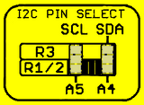
2. Change the cut-track jumper positions on the bottom of the PCB. Find the two sets of 3-way solder pads as shown on the right. There is a tiny copper track joining the middle and bottom pads of both sets, configuring the shield to connect to A4 and A5 so it's in "R2" mode. Using a sharp knife, carefully cut between the middle and bottom pad of each set so that the tiny track is cut. Then, use a soldering iron and solder to make solder bridges joining each of the middle pads to the pad above it. The shield will then be in "R3" mode, and will work with any R3 Arduino models including those like the Leonardo that don't work with R2 headers.


